


Semi-Rotational DC Voltage Transformer
This is to introduce a novel semi-rotational DC voltage transformer (Patent number:- EG/P/2025/1182) designed for efficient and inexpensive conversion of DC voltages from high to low and vice versa. The transformer addresses the limitations of conventional methods that rely on complex electronic circuits, which are often limited in voltage capacity and introduce distortions. The design incorporates a rotating primary core to cut and rotate the DC magnetic field, effectively converting it into a rotating field within the transformer. The device integrates auxiliary components such as a superconducting fault current limiter (SFCL), rectifier, and surge arrester to enhance performance and protection. This innovative approach enables the use of high-voltage direct current (HVDC) in electricity transmission and distribution and facilitates the integration of renewable energy sources. The patent is still pending and can convert the local application into IPC.
[1] DC current or voltage can't be converted/transformed by conventional electrical transformers. This is because DC voltage has a constant/stationary magnetic field that can't be cut through the copper coils of the transformer, thus transferring the voltage to the other core of the transformer. Conventional AC electrical transformers only transform alternating voltage to alternating voltage, but with different values.
[2] Electronic circuits used to convert/transform DC voltage to DC voltage, such as chopper circuits, only operate at low voltages and can't convert/transform voltages with large differences, as they are governed/limited by a conversion factor called the duty cycle, which is the result of dividing the connection/switching-on time by the total time (switching-on time + disconnection time). The value of this factor ranges from zero to 1, which means that such electronic circuits can't be used at medium and high voltages needed by transmission, distribution and generation stations to convert voltages with different differences, such as converting 220 kV to 120 kV or converting 66 kV to 11 kV.
[3] Electronic circuits used to transform DC voltage to DC voltage, such as chopper circuits, are expensive and produce distortions in the electrical network voltage, which prevents their use at medium or high voltages, thus being an obstacle to transmission using high voltage direct current known as (HVDC).
[4] A large inrush current is generated when the transformer is switched on. This current can be up to 6 or 10 times the rated current, and sometimes up to 20 times the rated current. This can cause faulty operation of the protection devices, which can cause the transformer or the network to go out of service until the problem is resolved. Naturally, this current can cause problems for the transformer itself, such as insulation breakage, coils melting, and thermal and mechanical stress.
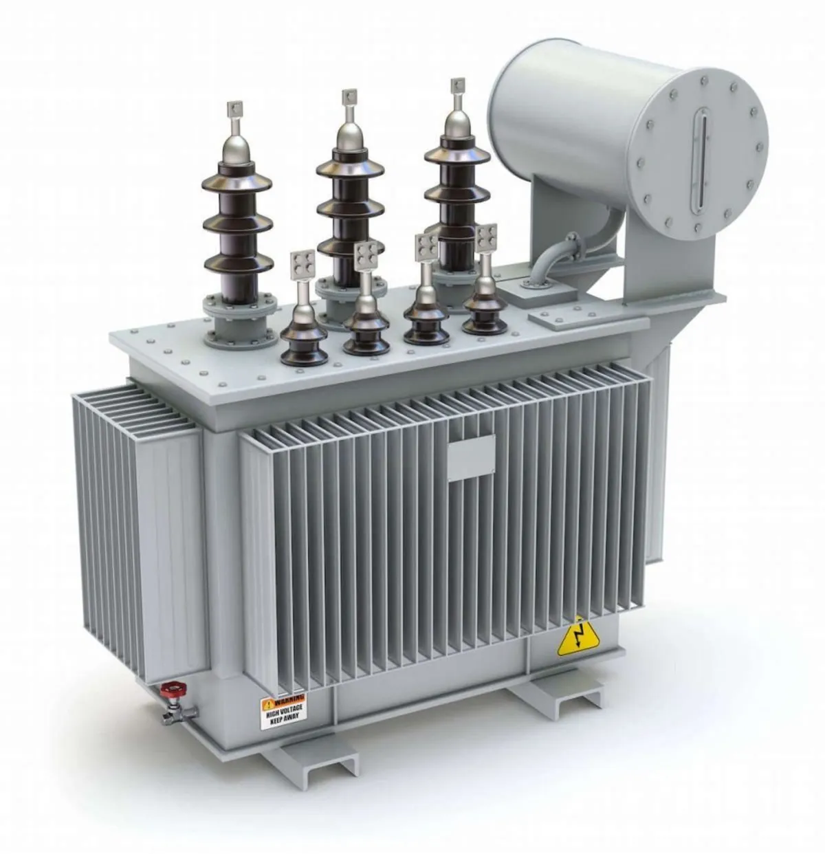
[1] The DC voltage transformer is similar in structure to the electrical AC transformers we are familiar with, except that its primary core is rotating, not stationary. This is done to cut and rotate the stationary DC magnetic field associated with the DC voltage, creating a rotating field inside the transformer. This rotating part resembles an electric motor; it drives a base with magnetic poles attached to it, which cut and rotate the stationary DC magnetic field. It can move without electricity, as fan blades are installed in the transformer and connected to the rotating part. Air can be used to move the transformer if it is in open spaces exposed to air, or water can be used to move it, as in dams. The invention here functions as an electric generator and an electrical transformer simultaneously, or it can use electricity from an external source, such as solar energy, to move the rotating part. The rotor can also rotate or move linearly in the vertical/y-axis, enabling a part/component of the transformer to cut the stationary DC magnetic field of direct current, thus transferring it to the other core with a different voltage value. Thus, the transformer operation principle is achieved.
[2] The transformer also contains auxiliary components in this invention, such as a superconducting fault current limiter to protect it from short circuit currents and inrush currents. It also includes a rectifier which is a rectifying circuit consisting of several diode units to convert the AC output to DC when needed. It also contains a surge arrester to protect the transformer from discharge voltages. Apart from these important components, the DC transformer contains all the protection and measurement devices that any other transformer contains, such as a current transformer (CT), a voltage transformer (PT), silica gel, a cooling medium, whether mineral oil, air, nitrogen, or any other type of cooling medium depending on the voltage used with the transformer, a Buchholz relay, and so on.
Yes, It makes a major gap as it can convert/transform DC voltage into DC voltage with higher or lower voltage levels using modified AC transformer (normal transformer + added parts) without the need of converter and inverter substations.
[1]The transformer's ease of use, low cost, and ease of inspection and maintenance for any malfunction. [2]The vast accumulation of knowledge in the transformer and motor rotor manufacturing industry facilitates qualitative knowledge shifts in this field, which will later help provide affordable electricity to all. [3]The ease of using high-voltage direct current (HVDC) in electricity transmission and distribution, thanks to the availability of a constant-voltage/DC transformer which was previously unavailable, will help expand the use of renewable energy sources. [4]The moving/rotating part of the transformer uses a circular base with magnetic poles attached to it to cut the stationary magnetic field associated with the DC voltage. The rotor can also rotate or move linearly in the vertical/y-axis, enabling a part/component of the transformer to cut the stationary DC magnetic field, thereby transferring it to the other core with a different voltage value. Thus, the transformer operation principle is achieved. The transformer in this invention includes several auxiliary components, such as a superconducting fault current limiter to protect it from short circuit currents and inrush currents. It also includes a rectifier to convert the AC output to DC output when needed, and a surge arrester to protect the transformer from discharge voltages. [5]The input of the transformer is DC voltage, and the output is an alternating/AC voltage. An electronic circuit consisting of a network of diodes can be added to unify the voltage, so the output becomes a constant voltage, which means it can be used in DC voltage networks and alternating/AC voltage networks. [6]A semi-rotational DC voltage transformer consisting of a secondary core and a primary core around which a rotating part rotates. The rotating part rotates around the primary core, which is wound with copper coils and passes a DC voltage; it is not a stationary primary core like other transformers. This is done to cut and rotate the constant/DC magnetic field associated with the constant/DC voltage, so that it becomes a rotating field inside the transformer. This rotating part is similar to an electric motor. It is a motor that moves a base (rotationally or vertically on the x-axis) with magnetic poles attached to it, which cut and rotate the constant DC field. It is possible for it to move without electricity, as there are fan blades installed in the transformer moving part and connected to the rotating part of the transformer to use air to move it if it is in open spaces exposed to air, or water to move it as in dams. The invention here works as an electric generator and an electrical transformer simultaneously, or it uses electricity from an external source to move the rotating part, such as solar energy, for example. The transformer also contains auxiliary elements in this invention, such as a superconducting fault current limiter to protect it from short circuit currents and inrush currents. It also includes a rectifier, which is a rectifier circuit consisting of several diode units to convert the AC output to DC output when needed. It also contains a surge arrester to protect the transformer from discharge voltages. Other than these important components, the DC transformer contains all the protection and measurement units that any other transformer contains, such as a current transformer (CT), a voltage transformer (PT), silica gel, a cooling medium, whether mineral oil, air, nitrogen, or any other type of cooling medium depending on the voltage used with the transformer, a Buchholz relay, and so on. [7]A semi-rotational DC voltage transformer, as mentioned in the first item, contains a rotating part around the primary core coils. This part is a circular base on which magnetic poles are fixed, producing a rotating magnetic field that cuts the stationary DC magnetic field associated with the DC voltage, transforming it into a rotating magnetic field inside the transformer. This allows the voltage to be changed and transferred from the primary core to the secondary core, like any normal electrical transformer. [8]A semi-rotational DC voltage transformer, as mentioned in the first item, provides an output in the form of a direct voltage or an alternating voltage, depending on the need. The output of the DC voltage transformer is an alternating voltage, and a current rectifier can be installed to obtain a direct voltage. [9]A semi-rotational DC voltage transformer, as mentioned in the first element, can rotate horizontally or vertically to generate a rotating magnetic field that cuts the fixed DC magnetic field, allowing the DC voltage to be converted and transmitted within the transformer. It can move without electricity, as there are fan blades installed in the transformer and connected to the rotating part of the transformer to use air to move it if it is in open spaces exposed to air, or use water to move it as in dams. The invention here works as an electric generator and an electric converter at the same time, or uses electricity from an external source to move the rotating part, such as solar energy, for example. [10]A semi-rotational DC transformer, as mentioned in the first item, is not affected by short circuit currents or inrush currents, which prevents the malfunction of protection devices and reduces the risk of transformer fires. This is because the transformer contains a superconducting fault current limiter, which is a resistance with a zero value during operation and a maximum value when short circuits or surge currents occur. [11]A semi-rotational DC voltage transformer, as mentioned in the first item, is not exposed to the problems of discharge voltages or voltages/overvoltage exceeding the rated voltage value of the transformer, as it contains a surge arrester to protect the transformer from discharge voltages. Other than these important elements, the DC voltage transformer contains all the protection and measurement units that any other transformer contains, such as a current transformer (CT), a voltage transformer (PT), silica gel, a cooling medium, whether mineral oil, air, nitrogen, or any type of cooling medium according to the voltage used with the transformer, a Buchholz relay, and so on.
Industries where the invention can be useful?
Transformers, Energy generation plants, Electricity transmission, Water DamsAn estimate of the total addressable market?
50,000,000,000 $USDPotential Customers/End Users. Who might benefit?
Transformers manufacturers, Power plants and substations
Documents
-
1765032194057_408.pdf
Actions
Added all portfolio
| Country | Current Status | Patent Application Number | Patent Number | Applicant / Current Assignee Name | Title | Google Patent Link |
| Egypt | pending | EG/P/2025/1182 | EG/P/2025/1182 | Mahmoud Ahmed Saad | Semi rotational DC Transformer | Not mentioned |
You may also like the following patent
Advanced Medium and High voltage Circuit Breaker
| Available For: Egypt | Energy and Utilities |
I propose a novel medium- and high-voltage circuit breaker capable of interrupting both alternating current (AC) and direct current (DC) using atmospheric air as the insulation medium. The breaker...
| Application Number | EG/P/2022/1486 |
| Patent Number | EG/P/2022/1486 |
| Current Status | Pending |